The previous note focused on the UV ellipse covered by a single pixel, establishing our baseline for texture sampling. This entry does not introduce a new sampler; instead, it shifts focus to the geometric illusion of depth. By utilizing a height field, we can offset UV coordinates along the tangent-space view ray to convince the eye that a flat, two-triangle quad is actually deeply carved brick. The combination of interior parallax and an optional height-field self-shadowing routine closely mimics true volumetric depth. However, this approach has a strict physical limitation: the outline of the mesh cannot change. Ultimately, the silhouette is still the quad.
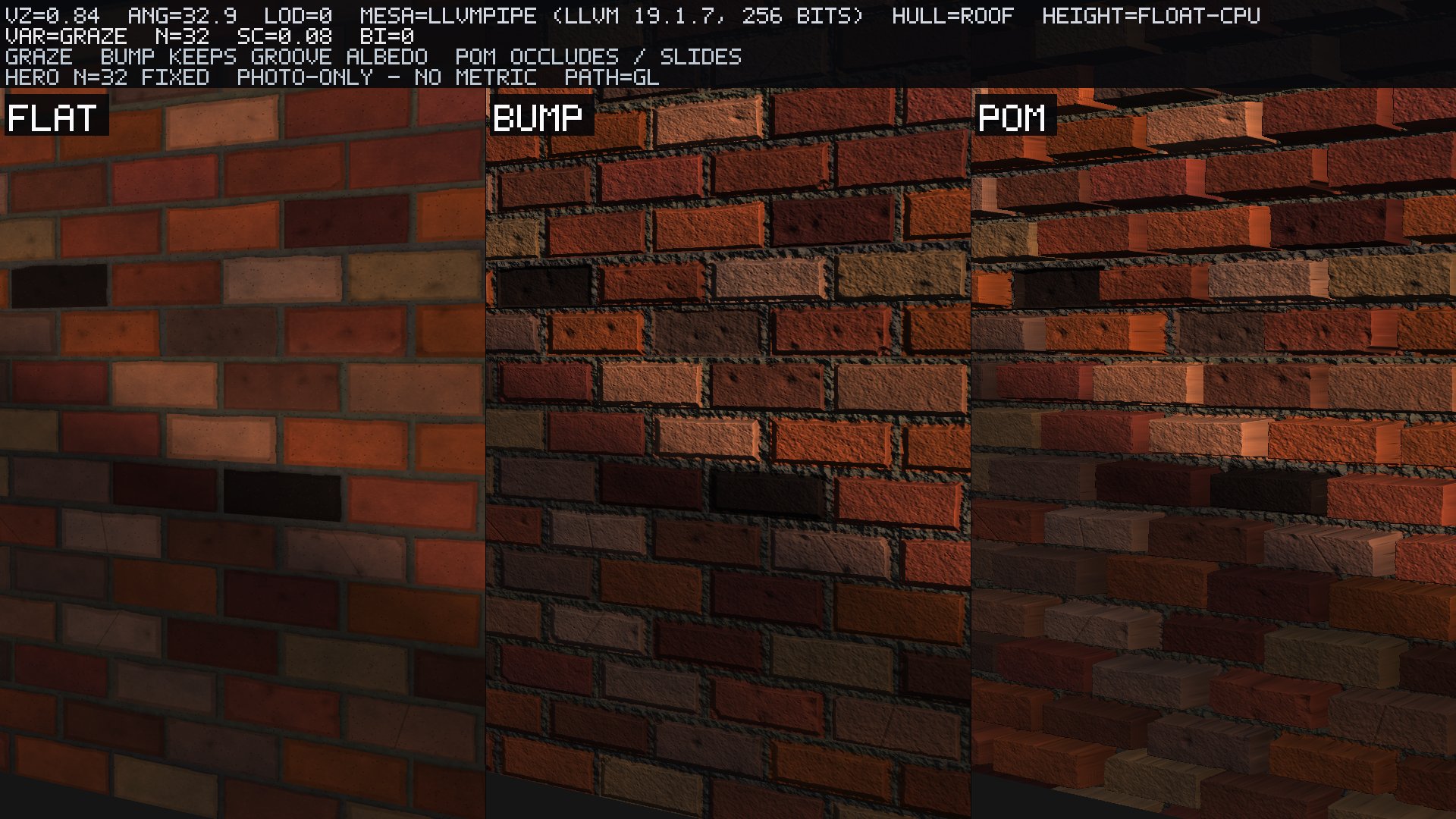
Consider the same brick wall under identical lighting conditions across three different shader implementations. On the left, FLAT rendering uses standard geometric and base UV to produce what is effectively a painted card where mortar wells remain fully visible regardless of angle. In the middle, BUMP mapping applies height-derived normals at the geometric UV. While the grooves receive realistic shading, the bricks themselves do not exhibit perspective shift or "walk" as the view angle changes. On the right, POM (Parallax Occlusion Mapping) utilizes an roof-hull march. Here, interior bricks slide correctly in perspective, and mortar realistically hides in the wells just as it should. Note that this visual comparison is strictly a photograph; do not attempt to derive a formal UV-error number from this frame.
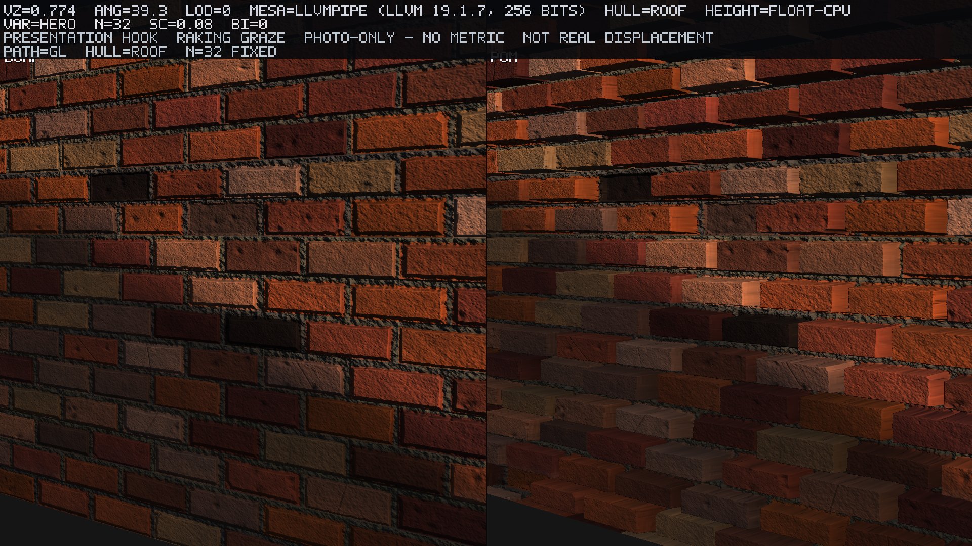
The visual takeaway here serves as the core thesis of this post: when comparing bump mapping against POM at a severe raking graze, the depth is striking, but it is unequivocally not real displacement.
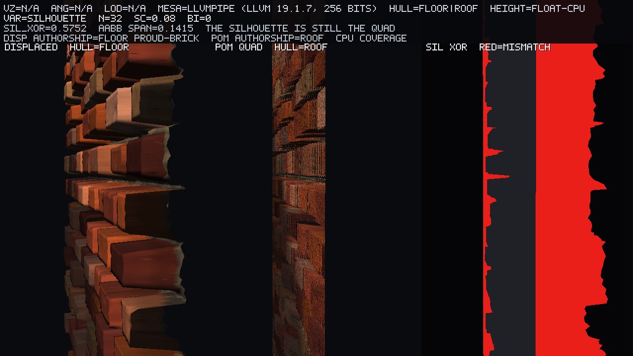
We can precisely measure this structural lie. On the left, proud bricks generated by a CPU-displaced grid physically extend the mesh's outline. In the middle, the POM quad remains a fundamentally flat card. The red highlight on the right illustrates the coverage discrepancy: . That calculated fractional difference is . The AABB span of serves as our mathematical proof of extrusion, verifying that the displaced grid genuinely left the basal plane. While interior pixels can register as a highly accurate POM hit, the actual screen-space coverage cannot organically grow beyond the base triangles.
Our hero configuration locks the scale at with a bias of , utilizing a fixed step count of . The height map format is R32F, executed on Mesa 25.0.7 llvmpipe. When viewed directly face-on, the Mean Absolute Error between bump mapping and POM is perfectly zero: MAE(bump, POM) . We measured analytic UV error on a spherical indent interior at a angle, demonstrating a clear convergence: stepping from at yields . At a grazing angle, the silhouette XOR (comparing the displaced floor against the POM roof quad) is . Throughout this testing run, internal validation remained pristine: 28 pass / 0 fail.
How it presents
The primary stimulus for these tests is a CPU-authored running-bond brick texture, sized at POT, utilizing REPEAT wrapping. It adheres strictly to the roof convention, where a height of is fully flush with the bounding mesh, and represents the deepest carved recess. For our rigorous scientific instruments, we employ a spherical indent (set to CLAMP_TO_EDGE) alongside a 1-D cosine ridge. The wall material itself is procedural clay, heavily layered with per-brick families, grog, and stria to ensure the UV sliding behavior has enough high-frequency detail to remain visible. It is deliberately neither a photo scan nor a standard PBR brick.
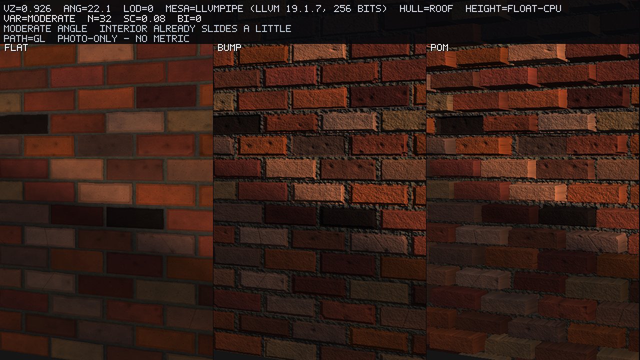
As shown above, interior parallax successfully creates the illusion of sliding geometry well before reaching the extreme grazing angles of the hero shot. This remains a photograph-only observation.
The rendering behavior strictly adheres to two regimes that must never be mixed:
-
Face-on (, ): The calculated UV offset is . In this orientation, bump mapping, offset mapping, steep parallax, and POM must match perfectly, sharing both the same normals and the exact same UV coordinates. Our scientific baseline confirms MAE(bump, POM) . If a so-called "POM" implementation somehow looks more 3-D from a dead-on perspective, either the TBN sign is inverted, or an erroneous residual offset is being applied.
-
Graze (): This angle is the primary focus of the article. Here, interior parallax delivers the highly sought-after volumetric "wow" factor, while the silhouette's disagreement with the mathematically displaced mesh reveals the inherent lie of the technique. Utilizing too few layer iterations in this regime directly results in texture swimming.
It is important to remember that a software rasterizer does not inherently have to animate to show flaws. Texture swimming at a completely locked pose manifests as visible banding and skipped mortar wells. Furthermore, the silhouette failure at a locked pose becomes painfully obvious as a perfectly straight polygonal edge resting right next to a seemingly complex, bumpy brick profile.
Fundamentally, standard height maps cannot represent overhangs, as they are strictly defined as 2D functions . Any self-occlusion observed in these renders strictly means "this specific ridge visually blocks that well from this specific ray direction," rather than representing a volumetric cave or true undercut.
Why: TBN, , POM lerp
TBN and tangent-space view
To correctly warp our UVs, we first require an orthonormal tangent frame evaluated at the fragment, with its columns defined in world space. We strictly lock the handedness to a right-handed coordinate system, enforcing .
The scientific TBN matrix evaluated here is strictly CPU-generated, derived either directly from the quad or the displaced-grid vertex. This ensures it is the exact same matrix provided to the shader as vertex attributes. You must not trust an llvmpipe dFdx calculation of the world position to act as your precision science TBN.
For the front face calculation: . If , the ray is pointing away, and we immediately skip the march.
Height convention (roof default)
By default, the geometric quad acts as the outer hull stationed at a normalized height of . The sampled texture represents the structural elevation of the actual surface: where flush with the hull, and deeply carved in.
Here, represents a height bias, which is firmly locked to for the entirety of this run. The scale factor dictates the physical height range, measured in units of the quad’s -edge world length. Our locked hero metric requires . The required lateral UV travel to account for a unit drop in normalized height is given by:
Proud-brick silhouette control: We establish a secondary authored mesh stationed at the floor (height ), with individual bricks geometrically extruding outward to . This uses the exact same scale . This secondary geometry forms the literal outline that should organically grow under POM, but mathematically does not.
Handling misses: if the cast ray manages to completely traverse the internal volume without intersecting the height field, we gracefully fallback and sample the floor at .
Ray in the height volume
The ray begins its journey with its origin at the geometric hit location, stationed on the roof where , mapping to initial UV coordinate . The progressing parameter defines the normalized depth driven into the volume, equating to a direct drop in height:
A confirmed hit is registered at the absolute smallest value of that satisfies the inequality .
Offset mapping — named knife, not hero
When discussing true parallax mapping (Kaneko-style), which relies on a single sample, the UV perturbation follows:
Traditional offset limiting (often associated with Welsh) deliberately drops the term, resulting in a modified vector where . At severe grazing angles, true single-sample offset explodes into visual chaos, whereas the limited offset inherently under-walks the surface. Both historical methods belong documented on the family strip for context, but neither serves as the modern hero technique.
Steep parallax — even layers, first crossing
Steep parallax mapping discretizes the volume into uniform strata:
A steep hit is defined simply as the smallest layer index where the ray plane dips below the surface: . This produces a distinct mathematical staircase in . Our hero configuration fixes , while maintaining a strict compile-time cap of .
POM — linear search + secant lerp (hero)
After successfully isolating the first height-field crossing occurring between layers and , POM improves precision by interpolating the exact zero of . This assumes both functions maintain linearity with respect to across the tiny interval:
It is critical to understand that this is purely a secant step performed on the bounding samples; it is not an analytically perfect ray–height intersection unless the underlying height map happens to be perfectly linear between those two UV coordinates. Relief mapping (which utilizes binary bisections after identifying the initial crossing) is fully implemented in our backend but is intentionally omitted from the family strip comparison. The simplified ladder clearly demonstrates how a basic linear search can carelessly skip over a thin mortar well.
Sampling the height inside the march
When implementing the loop, you must not rely on standard texture() calls. Because the iteration count is highly non-uniform across varying fragments, calculating implicit derivatives inside the loop is strictly illegal. Instead, you must explicitly specify the LOD:
We enforce two tightly locked values for our comparisons:
-
: This preserves incredibly sharp wells but aggressively aliases when the wall is minified at a distance.
-
: This is derived precisely from the geometric UV Jacobian (CPU , utilizing the exact same formula standard mipmaps or anisotropic filtering would use). Under this LOD, relief noticeably melts and self-occlusion details fade out.
Do not falsely claim this calculates an accurate along-ray cone LOD. Following the resolution of , we sample the albedo at , and we derive the normal by evaluating the central differences of the height map exactly at the hit coordinate.
Self-shadow (second march, not a shadow map)
To simulate self-shadowing, we initiate a secondary ray marching from directly toward the incoming light vector in tangent space, bounded by the exact same roof/floor volume. If any subsequent sample along this secondary ray dips below the height field before fully exiting the volume, we classify the fragment as being in a height-field shadow. A simple binary result (any hit equals shadow) serves as our default approach. This technique is strictly in-family to parallax mapping; it should never be confused with shadow-map bias, PCF filtering, or standard glPolygonOffset hacks.
Silhouette predicate (the lie, as a formula)
To formally define the inherent visual lie of POM, let represent the absolute screen-space coverage of the base 2-triangle wall. POM can only shade fragments where . Conversely, let represent the true rasterized coverage of a highly tessellated, physically displaced grid possessing the exact same height data.
While manipulating gl_FragDepth based on the intersection distance can successfully correct interior depth testing for subsequent post-processing and compositing, it fundamentally cannot expand the rasterized coverage of the mesh. Our default rule is strict: do not write gl_FragDepth, and this current test run firmly abstains from doing so.
Unique artifacts: the slice, then the XOR
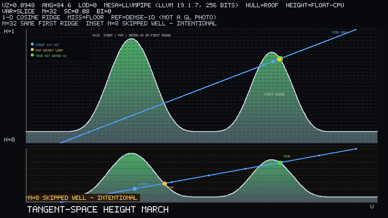
The diagram above illustrates the exact mathematical artifact this article was written to investigate. This is pure CPU science evaluation, deliberately untethered from a standard GL photo. It maps a 1-D cosine ridge against the incoming view ray and discrete layer planes.
-
Primary Validation: At , the Steep first-hit, POM secant lerp, and the dense-1D true intersection all mathematically agree on the same first ridge (indicated by the nested rings). The dense-1D resolves at , POM closely follows at , and the steep approximation lands at .
-
Inset Failure: The inset demonstrates a skipped well, which is entirely intentional. The mathematically true hit should still land on ridge 1; however, both the steep and POM algorithms completely jump the gap and erroneously skip to ridge 2. Providing the algorithm with too few layers is not evidence that "POM is broken"; rather, it is exactly the mechanism behind the texture swimming artifact we observe on the lower rungs of the -ladder.
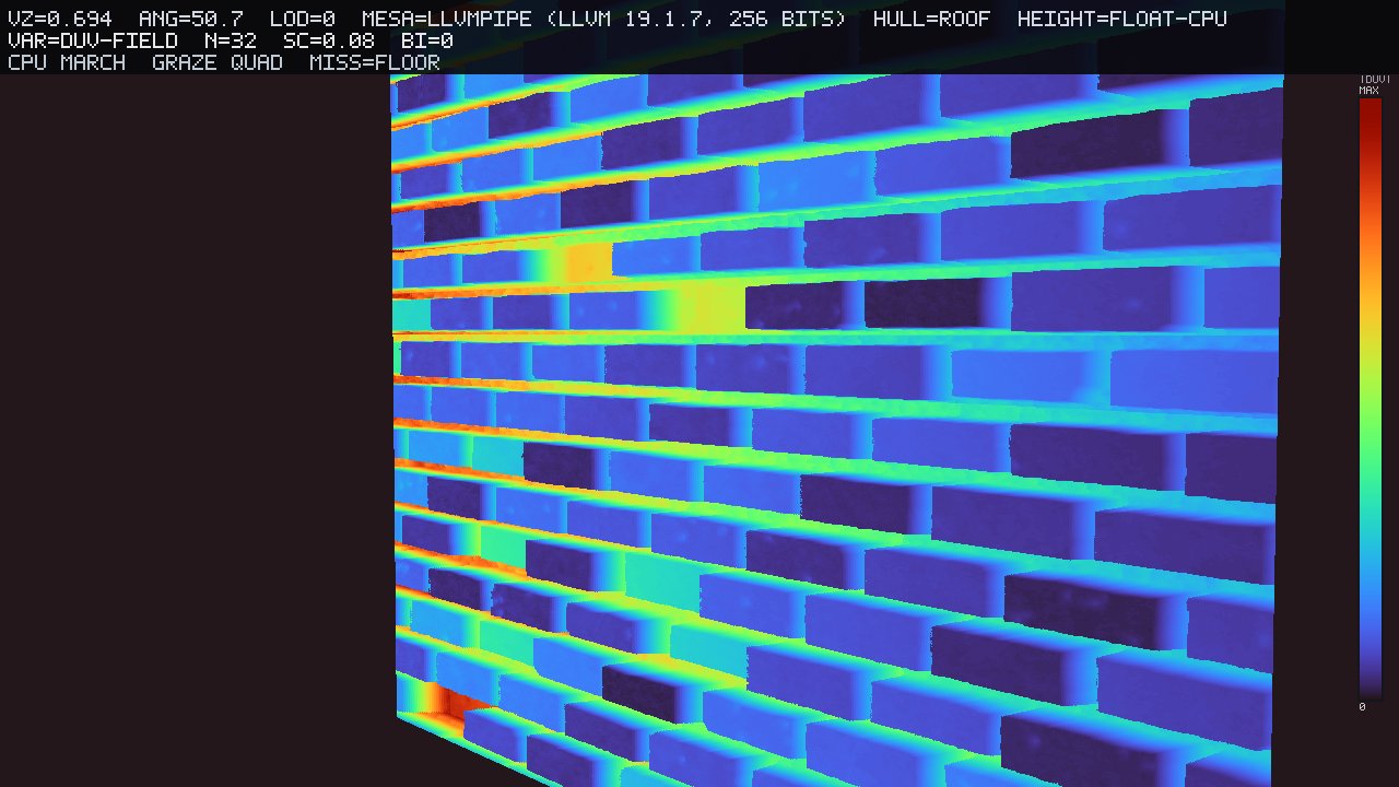
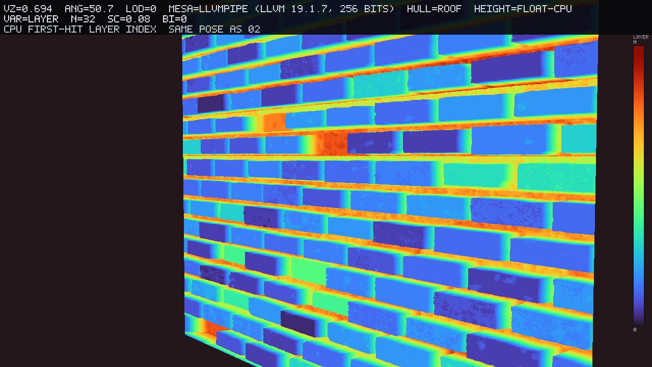
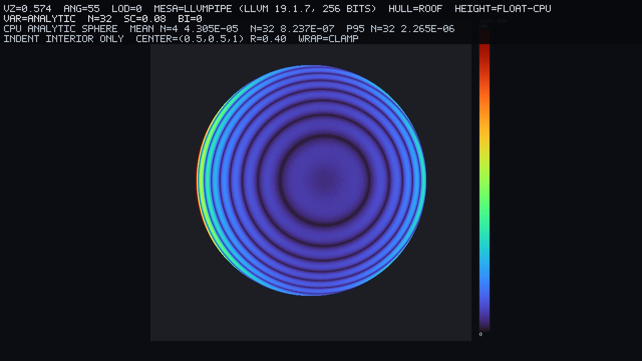
To rigorously evaluate UV error, we mapped a spherical indent with radius , perfectly centered at , using wrap clamp rules, evaluating the indent interior only. The generated heat map visualizes the deviation vector magnitude: . Any region outside the defined rim is considered the flat roof (); therefore, a raw quadratic sphere formula "miss" does not represent a valid height-field hit and is strictly excluded from our average error metrics.
Quote the numbers. Do not quote the brick photographs as UV error.
Operating with a locked scale , zero bias , under Mesa llvmpipe rendering:
| row | angle | metric | value | |
|---|---|---|---|---|
| POM indent interior | 4 | mean UV err | ||
| POM indent interior | 32 | mean UV err | ||
| same | 32 | p95 UV err | ||
| sil-xor floor vs roof | 32 | profile | fraction | 0.575 |
| face-on | 32 | MAE(bump, POM) | 0 | |
| face-on | 32 | sil XOR (not the lie) | 0.029 | |
| POM field | 32 | mean first-hit layer | 9.06 | |
| shadow | 32 | agree vs , same field | 0.993 |
For clarity, the hero rounding confirms that shifting from at yields a vast improvement to . The silhouette discrepancy is heavily pronounced at , with the AABB span confirming extrusion at . We assert mathematically that an . It is imperative to remember that this analytic error is derived exclusively from the sphere indent instrument, not the noisy brick texture. Do not attempt to invent a generalized GL UV error metric by squinting at the graze or brick-hero photographs; those specific frames are provided strictly for qualitative photo-only analysis.
Do not invent a subjective “POM quality score.”
Family, then the ladders
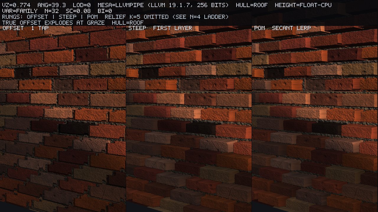
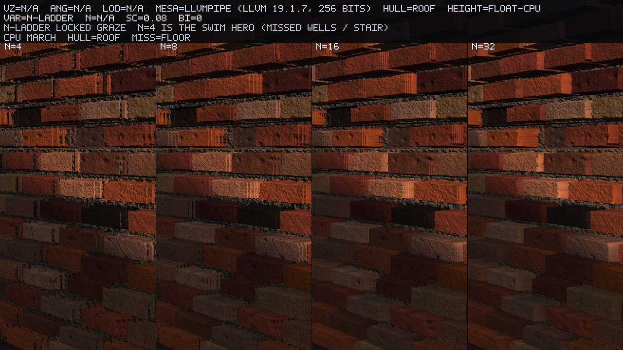
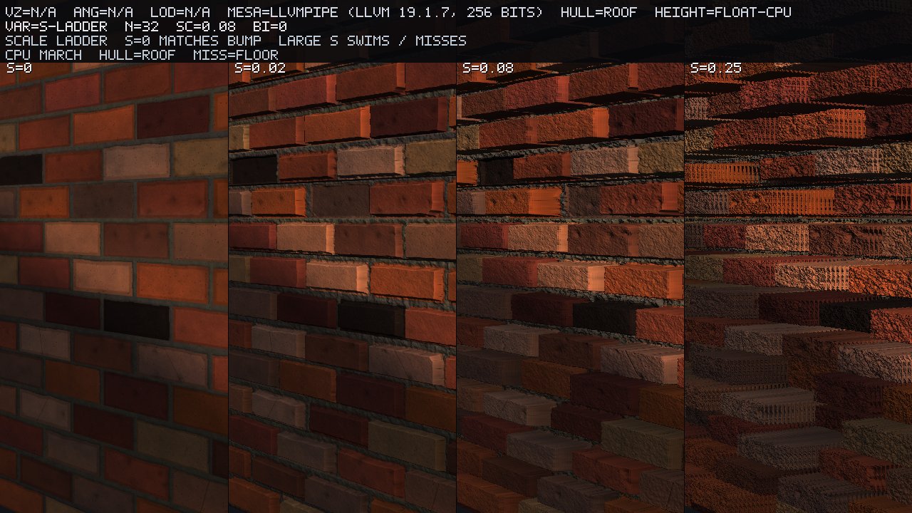
Controls
Face-on: POM must not invent depth
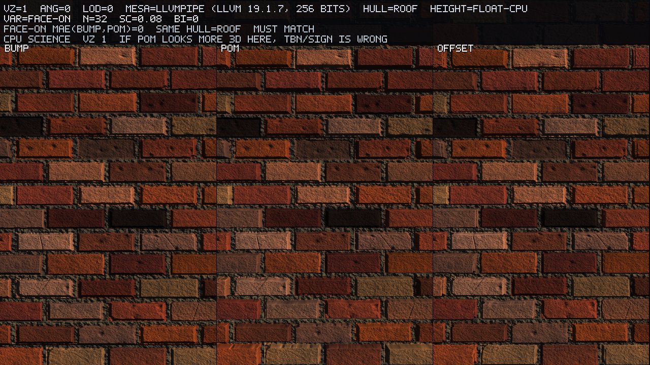
When the view vector perfectly aligns with the surface normal () utilizing the exact same roof hull, there should be zero UV deviation. The rigorous science path for this is an orthographic UV-grid calculation yielding MAE, not relying on a perspective photograph. This confirms MAE(bump, POM) . Note that the included photograph inherently captures a few microscopic degrees of edge parallax due to perspective projection; it serves as a visual picture of the control environment, not as a secondary quantitative metric. If your POM implementation mysteriously appears more 3-D or distorted here, verifying the TBN handedness should be your immediate first debugging step.
Scale / bias
A scale of is functionally equivalent to bump mapping, as it dictates absolutely no UV walk. Our strictly locked hero scale of strikes the ideal balance, providing highly readable interior parallax across this specific brick wall. Pushing the scale to forces the ray to span far too many repeating tiles per unit of depth : the initial ray crossing erroneously intersects the wrong brick entirely, rays smash directly into the volume floor, and the entire wall violently swims. Bias remains rigidly locked at .
Too few steps
Executing the march with only layers completely misses deep wells and creates massive staircasing artifacts, serving as a highly visible spatial proxy for swimming. Increasing the sample count to beautifully cleans up the exact same pose. The earlier march-slice featuring the inset is a direct mathematical representation of this exact failure mode occurring in 1-D; it is explicitly labeled as an intentional failure so that it cannot be mistakenly read as a broken hero implementation.
Self-occlusion is a second height march
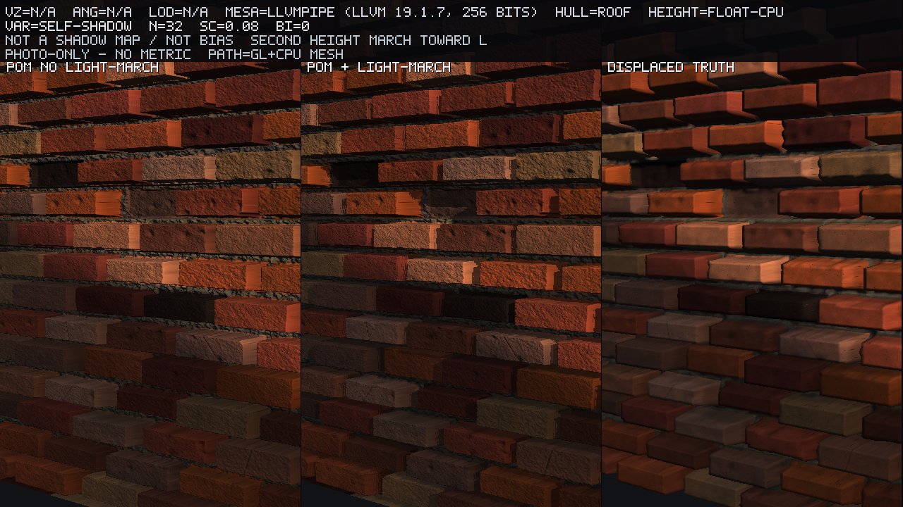
The image sequence above demonstrates the bounds of self-shadowing. On the left, with only the view-march active, physically hidden wells can erroneously receive full shading if the view hit is successful but the incoming light angle is completely ignored. The middle frame introduces the secondary light-march, which correctly darkens the contact points and deep recesses. The right frame provides the displaced-mesh truth, utilizing real triangulated geometry matching the exact same height field. As the caption firmly states: this is not a shadow map. Our reported shadow agreement of is specifically derived by comparing an march against a denser march operating on the same underlying height field, not by comparing it against ray-traced geometric triangles. Do not quote this agreement metric as a validation of geometry matching.
Height LOD — one sentence of Jacobian
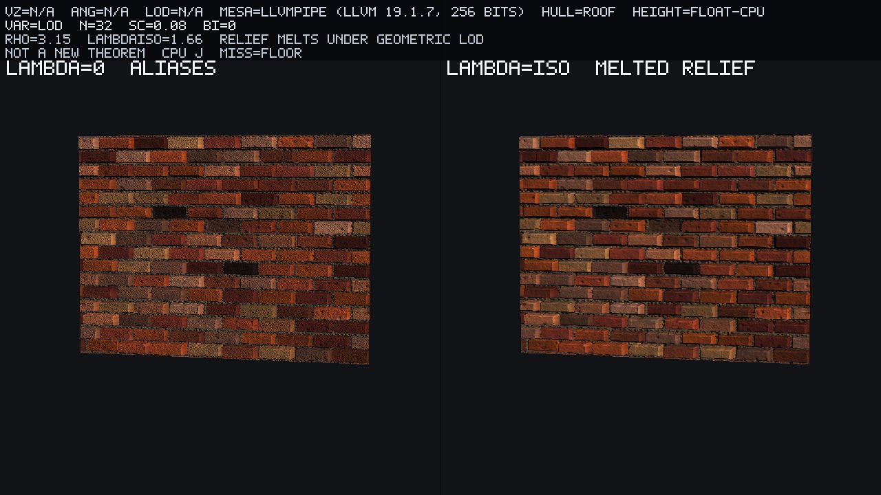
When the wall is minified at a distance, the CPU calculates the geometric UV Jacobian as , which yields an isotropic LOD of . On the left, clamping to preserves the incredibly sharp mortar wells but introduces severe aliasing artifacts. On the right, adopting causes the high-frequency relief to melt and soften significantly. This ensures perfect continuity with standard mipmaps and anisotropic filtering: it applies an isotropic LOD based entirely on the geometric UV footprint, completely ignoring any complex along-ray cone calculations. This is standard practice, not a new rendering theorem, and we present no extensive Anisotropic Filtering quality tables here.
Offset leaves the tile
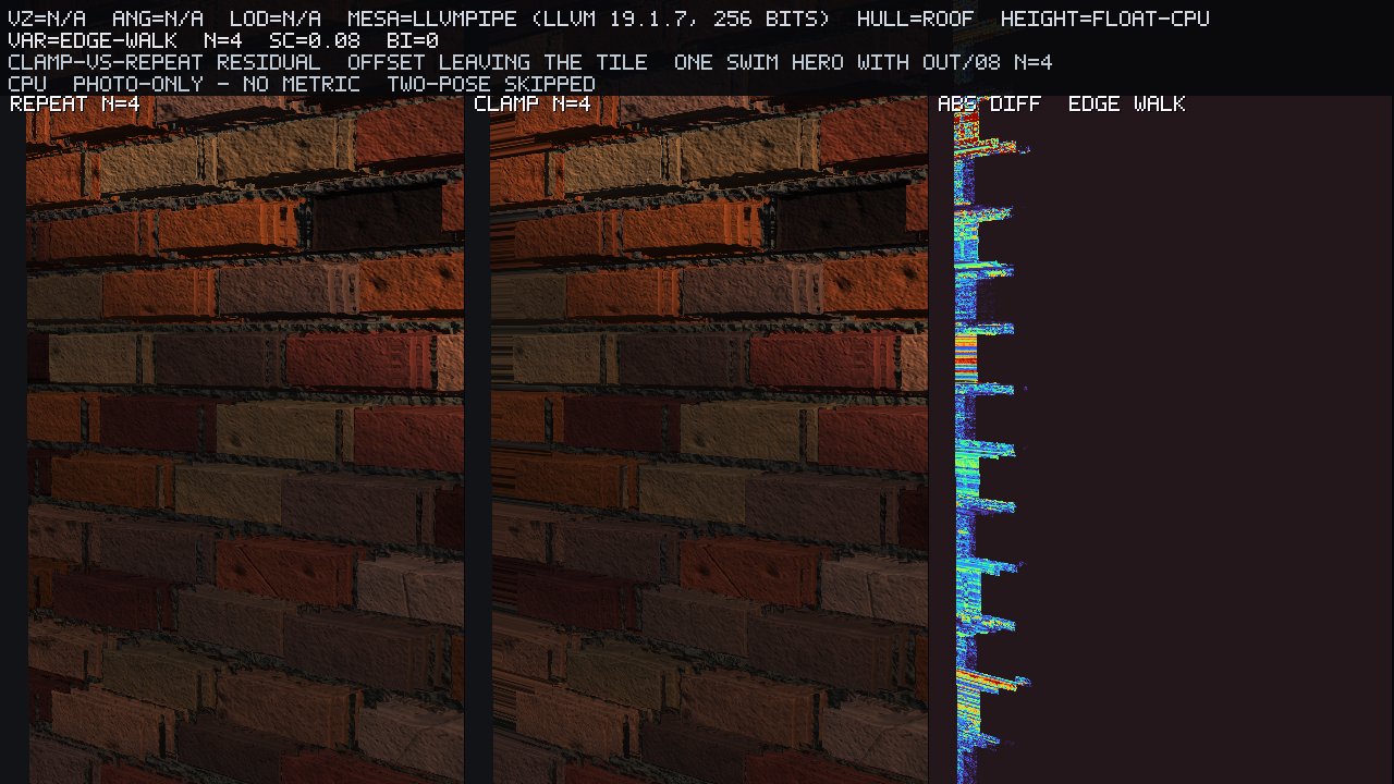
When a ray pushes past the boundary, a periodic brick texture should naturally walk over to the next repeating tile; utilizing a strict clamp instead flattens the boundary into an ugly rim. This remains a photo-only observation.
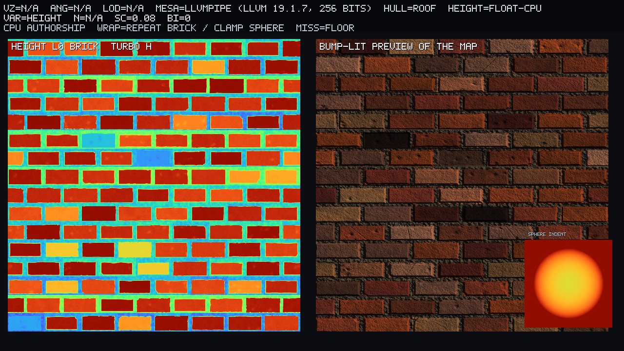
What this box actually measured
To ensure total transparency, the host environment for these evaluations was OSMesa, running Mesa 25.0.7-2+deb13u1, utilizing the llvmpipe driver (LLVM 19.1.7, 256 bits). The framebuffer target was strictly RGBA32F, with height map uploads locked to R32F. The 8-bit fallback path was not hit at any point during testing, and we deliberately disabled sRGB and MSAA. The depth buffer gl_FragDepth was not written. The primary brick texture utilized REPEAT wrapping, while the spherical indent instrument used CLAMP_TO_EDGE. Our automated assertions confirmed 28 pass / 0 fail, mathematically validating that the TBN matrix remained perfectly orthonormal and right-handed, verified that , confirmed that the displaced AABB span was properly (0.1415), proved the analytic UV error decreased properly as , established the face-on MAE precisely , and confirmed the grazing profile (measuring at 0.575).
We can firmly claim: operating on this specific OSMesa / llvmpipe build, a rigorous CPU tangent-space height march applied to an authored field successfully offsets UVs along a perfectly known vector . This reduces measurable UV error compared to an analytic sphere as the layer count grows, right up until the linear-search / lerp model inherently saturates. Implementing a GLSL 330 fragment march constrained by a fixed step cap and relying on textureLod produces what is effectively a photograph of this software rasterizer, and should not be misconstrued as testing a discrete GPU’s dedicated POM hardware unit (because no such hardware unit actually exists). In a perfectly face-on orientation, bump mapping and POM flawlessly match along our scientific evaluation path (MAE ). At a heavy graze, the true physically displaced-grid coverage fiercely disagrees with the visual output of the flat 2-triangle POM quad; this resulting XOR delta completely encapsulates the silhouette lie. Implementing a secondary height-field light-march convincingly darkens mortar wells that the primary view ray fails to hide, but this technique fundamentally remains a ray march, not a hardware shadow map.
We absolutely cannot claim to have evaluated NVIDIA / AMD / Intel hardware POM implementations, nor can we quantify hardware tessellation quality or make sweeping claims that "AAA games do exactly this many taps." We cannot claim that our specific llvmpipe loop performance has any parity with a modern GPU, which is why we present zero millisecond frame timings. We cannot assert that a shader utilizing dFdx/dFdy to build a TBN matrix, or relying on implicit LOD calculations inside a dynamic loop, will exactly match dedicated hardware behavior. We cannot claim that the standard POM secant lerp is a perfect analytic ray–height intersection. We cannot state that writing gl_FragDepth out from the shader magically "fixes" the lack of true displacement—the absolute screen coverage is, and always will be, bottlenecked by the primitive quad. Most importantly, we cannot claim that a height field is actual geometry.
Honesty, short:
-
Metrics are CPU evaluated exclusively on float height data. The presented graze shots, brick-hero panels, and self-shadow wall comparisons are essentially gorgeous photographs of this specific software rasterizer in action. Do not irresponsibly quote these qualitative images as a quantitative UV error or metric.
-
Face-on MAE is exclusively the UV-grid control. The accompanying perspective face-on photograph is simply a visual picture of that isolated control environment, absolutely not a second measurable metric.
-
Analytic UV error is strictly scored inside the spherical indent interior only. The POM secant lerp is fundamentally not a perfect ray–height intersection, making the residual error compared to the true analytic solution fully in scope for this evaluation.
-
March-slice “analytic” data represents a dense 1-D mathematical first-crossing of our precisely authored cosine ridge, not a perfectly closed-form sphere.
-
Silhouette XOR inherently requires a profile camera to be measured accurately. The minor face-on XOR of is simply edge noise and is not the true architectural lie we are examining. The AABB span being mathematically stands as our definitive extrusion proof.
-
Self-shadow agree simply pits an march against a heavier march on the exact same underlying field; it is not a comparison against a physically displaced mesh and it is absolutely not a hardware shadow map.
-
Height LOD. Evaluated at , yielding . The resulting relief softening is quite visible but remains functionally modest. This relies entirely on the geometric Jacobian only.
-
Scale is tightly locked to provide readable interior parallax across this specific wall asset. Cranking the scale to intentionally hits the swim/miss failure rung for educational purposes.
-
No
gl_FragDepth, no cone-step, no tessellation. The absolute physical coverage of the POM rendering path strictly remains the flat 2-triangle quad. -
Brick is CPU procedural, explicitly not a high-fidelity photo scan. Analytic error was measured purely on the mathematical sphere, not on the noisy brick asset.
Bump mapping merely perturbs the normal at the existing geometric UV coordinate. Offset mapping applies a single naive push. POM continuously marches through a mathematical volume. True displacement physically moves the geometric vertices. Only the last technique is physically capable of growing the mesh's silhouette.
Pin the graze 3-up as the definitive presentation. Pin bump-vs-POM as the ultimate lighting hero shot. Pin the silhouette XOR comparison as the stark, mathematical lie of the technique. Pin the 1-D march slice accompanied by the analytic UV-error heatmap as our rigorous science theorem. The foundational formula serves as the caption, and the XOR fraction perfectly encapsulates exactly why the mesh's outline stayed a flat quad.